* D-Sub 케이블                                                         * 컴포넌트 케이블


▶ 컴포넌트 선 3개

빨간색, 녹색, 파란색 3가지로 구성되어 Y, Pb, Pr 신호를 전송해주며 DVD에서 많이 사용하는 Component 신호는 색깔은 단자가 R/ G/ B로 되어 있지만 Y 는 밝기, Yb or Pb (청색편차신호), Yr or Pr (적색편차신호) 가 전송되고 G 에 해당되는 것은 편차 신호를 수식으로 해석해서 다시 계산을 하는 방식입니다 

▶ D-Sub 와 컴포넌트의 차이

D-SUB은 한개의 케이블안에 15가닥의 얇은 통신용 전선이 들어 있어서 이 선을 이용해서 신호를 보내는 방식.가까운 거리라면 몰라도 먼걸리는 노이즈가 생김. 

콤포넌트는 색차영상출력이라고 해서 화면을 구성하는 신호중에 흑백의 밝기신호(Y)와 색차신호1(Pb)와 색차신호2(Pr) 3개의 신호를 각각의 별도의 선을 사용하여 신호를 전송 콤포넌트는 선하나에 신호와 그라운드(신호보호용-노이즈방지)가 같이 있어서 D-SUB보다는 멀리 보낼때 유리 하지만, 가까운 거리라면 D-SUB나 콤포넌트나 똑같음

'하드웨어 > PC 관련' 카테고리의 다른 글

S-video to composite video adapter  (0) 2009.03.18
Component and Composite Video Cable  (0) 2009.03.18
VGA Description and Pinout  (0) 2009.03.18
DVI Connector PinOut and Signal Names  (0) 2009.03.18
블로그 이미지

맨오브파워

한계를 뛰어 넘어서..........

,

Designed by Tomi Engdahl
First published in Internet at 1999, last updated at 2006

This simple adapter can be used to convert Y/C video (S-video) to a composite video. This adapter is useful in cases where your video output device has only S-video output but your signal source accepts only composite video input. This circuit works with both PAL and NTSC video standards.

Y-ground------------------+
                          +---------- RCA/composite ground
C-ground------------------+

Y-------------------------+
                          +--------- RCA/composite video
C------------||-----------+
            470pF
This circuit can be quite easily build inside a the S-video connector case if a physically small size 470 pF (ceramic) capacitor is used. Larger capacitor values will also work, but cause picture to become "softer". The voltage rating of capacitor can be 10V or more.

This circuit works in practice quite well even though the circuit operation is not ideal. This means that impedances and signal levels not matched exactly right, but near enough to work accetably. The picture quality you get from this circuit is is good, but not as good as with best possible composite video output circuitry.

Here is the pinout of the S-video connector shown from the end with the FEMALE PINS (picture is a view on the equipment back/front panel):

S-video DIN connector

1   Y ground
2   C ground
3   Y (luminance+sync)
4   C (crominance)

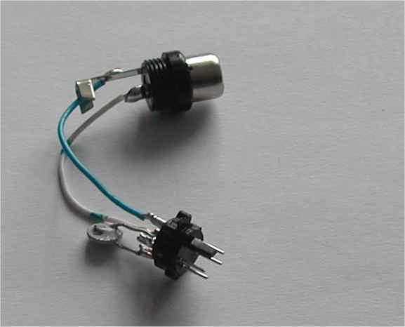
Picture of built circuit

This circuit version is juts built to be an example how the circuit can be built. If you built it yourself you might want to use components that fit nicely inside the connectors casing and build the circuit so that you cna put the connector cases in place. If you plan to have distance more than few centimeters between the connectors, it is a good idea to use shilded signal cable (75 ohm coaxial cable is the best, shielded audio cable works well to distance up to few meters).

image1

Can I use different capacitor values ?

The circuit diagram lists the capacitor value 470 pF. Somewhat different capacitor values would also work. Practically all capacitor values form around 400 pF to around 10 nF should work somehow acceptably.

Can I buy ready made adapters like this ?

I don't have ready made circuits for sale. Ready made circuits are nowadays avaialble at video/hifi shops and form computer shops quite cheaply nowadays (3-10 Euros/Dollars). For example www.svideo2rca.com has this kind of devices for sale on-line.

Are there ways to improve S-video to composite video conversion ?

Some ICs that do S-video to composite conversion internally use luma trap to eliminate cross color artifacts. With a properly designed luma trap, the conversion works somewhat vetter than with my simple circuit. One IC that implements luma trap is AD725 from Analog Devices. The IC data sheet has information on luma trap design. When luma trap is used, the luma trap needs to match the video standard (PAL and NTSC) being used. For a filter that will work for both PAL and NTSC a means is required to switch the tuning of the filter between the two subcarrier frequencies.

My simple circuit described above works for all video standards without modifications. I have not designed any circuit that used this luma trap method myself and I have no plans to add this to my circuit.

What if my PC graphics card has a 7-pin S-video connector instead of 4-pin ?

The four pin S-video connector as shown above is the standard connector for carrying S-video. Those seven pin connectors seen on some PC graphics cards are non-standard connectors for carrying S-video. The use of the pins on those seven pin connectors is not standardized and can vary from manufacturer to manufacturer. (For some strange reasons some manufacturers in PC industry just keep constanly breaking the industry standars and create lots of confuzion to users when doing so).

Generally the four pins on those 7-pin connectors on the same places as the standard four pin S-video connector have practcly always the same fuctionality as those pins in S-video connector. The other three pins can have then some extra signals which are not part of S-video (usually some pins of those carry composite video and some control signals, but the use of those three extra pins vary quite much). So if you encounter 7 pin connector for S-video, then forget the three center pins... just use the four on the standard positions. The circuit shoudl work with those connectors as well.

I am using the adapter ans still do not get colors. What is wrong ?

This adapter is designed to convert S-video signals to composite video. And it has proven to work well on this. This circuit cannot solve other possible incompatibility issues that you might have. A typical problem that causes black and white video instead of color is incomatible video standards on the signal source and the receiver. If your video signal source (for example PC video card TV output) puts out NTSC video but your TV is designed to handle only PAL standard you get usually black and white image, and with some devices video signal does not sync at all. PAL signal to NTSC TV does not work either. One very common problem with computers that have TV putput is that the default output video standard is not right for your TV. If you get problems with computer TV output, configure your video output to right standard that your TV supports and try again. The exact details how o do this configuration varies between different computers and graphics cards. Consult your computer user's manual and other documentation for exact details.


'하드웨어 > PC 관련' 카테고리의 다른 글

RGB to 컴포넌트케이블 차이점  (0) 2009.03.18
Component and Composite Video Cable  (0) 2009.03.18
VGA Description and Pinout  (0) 2009.03.18
DVI Connector PinOut and Signal Names  (0) 2009.03.18
블로그 이미지

맨오브파워

한계를 뛰어 넘어서..........

,

Component Video


Component Video is also called YPbPr, or YCbCr and transmits the picture information in a luminance and phase-opposite chrominance pair over three coax cables [Red, Green, and Blue]. RGB [Red, Green, Blue] is some times also called Component Video, but combine the color, black and white signal

YPbPr is 'sometimes' used when discussing the three-wire analog video component interface EIA-770 [EIA-770.2-a SMPTE-240M and others]. The luminance (Y) is represented separately from the color components (Pb and Pr).
In some cases The Y output is provided as a Green jack, the Pb is provided as a Blue jack, and the Pr is provided as a Red jack. The 'Y' signal carries the black and white information, The 'Pb' and 'Pr' signals carry the color difference signals.

YCbCr is used when discussing a digital component interface ITU-601 or ITU-656 digital interfaces (formerly CCIR-601, CCIR-656). Y is Luminance, Cb is Blue Chromanance, and Cr is Red Chromanance. CCIR-601 defines an 8-bit DIGITAL 2's compliment coding for component video

RGB is the component format in which the primary colors (red, green, and blue) are transmitted as three independent components. The color, black and white signals are combined within these three signals. Only using RGB inputs requires separate horizontal and vertical sync inputs. RGB presents a better [TV] signal than the other forms of Component video, S-Video, Composite Video, or RS-170. RGB sends each signal on a separate cable and does not mix the color signals.


Component Video Cable

{Video Bus Index}


Composite Video

Single "Yellow" (shielded) RCA jack [75 ohm coax cable], which is not to be confused with the Audio (Red and White) jacks of the newer three cable systems, or just a single black wire in the older systems. It's a composite of the black-and-white information (Y) and the color information (C). Composite Video may also be called VBS [Video, Blanking and Syncs], or CVBS [Color, Video, Blanking, and Sync]. S-Video is better than Composite Video, and Component Video is better than either of them


 Composite Video Cable


Composite Video Cable


'하드웨어 > PC 관련' 카테고리의 다른 글

RGB to 컴포넌트케이블 차이점  (0) 2009.03.18
S-video to composite video adapter  (0) 2009.03.18
VGA Description and Pinout  (0) 2009.03.18
DVI Connector PinOut and Signal Names  (0) 2009.03.18
블로그 이미지

맨오브파워

한계를 뛰어 넘어서..........

,
Video Graphics Adapter [VGA] interface is used as an interface between a Personal Computer and a Monitor. The VGA interface was introduced in 1987 which was followed by Super VGA [SVGA] in 1990. So the signal pinout listed on this page is obsolete, use the pin out on the SVGA page instead.

VGA is a superset of EGA, incorporating all EGA modes. Older displays sent digital signals to the monitor, while VGA and later standards send analog signals. This change was necessary to allow for more color precision. The EGA video display interface is OBSOLETE.

The VGA interface provided a resolution of 640 x 480 pixels at a bandwidth of 36MHz, with the SVGA screen resolution having 800 x 600 pixels at a bandwidth of 45MHz. The VGA Interface bus uses either a 9-pin or 15-pin D-sub connector. The table below provides the pinout and signal names for either the DB15-pin or DB9-pin video connector.

The connector may be advertised having a number of different options. Assuming a 15-pin VGA connector on both the Monitor and PC; the cable will indicate 15 pins. The 15-Pin connector will have 3 rows of 5 pins or sockets. DB is the family, HD [High Density] is the style, M is Male [Pins], F is Female [Sockets]. Normally Equipment [PCs and Monitors] use sockets, so the cable needs to have pins [Male] to mate with the device. A normal cable may indicate HD15 Male to HD15 Male, or DB15 Male to DB15 Male, or high-density DB15 connector. In some cases the connectors may be called a mini-sub D15. The conductors will be 28 AWG in size. The length of the cable will vary depending on the quality, the better the cable is made the longer the length. When the cable uses a 15-pin connector and indicates a certain resolution then it may also comply with the SVGA standard. A Shielded cable is better then a non-Shielded cable. The cable may also indicate it contains EMI beads to reduce noise, again it may be a higher quality cable.

A listing on OEM D-sub connector manufacturers may be found on the Connector Manufacturers page, and this page points to Cable Assemblies.


VGA Cable

VGA Connector Pin Out
Pin # 15-Pin D 15-Pin D ---- 9-Pin D 9-Pin D
--- Name Description ---- Name Description
1 RED Video Red Video ---- RED Video Red Video
2 GREEN Video Green Video ---- GREEN Video Green Video
3 BLUE Video Blue Video ---- BLUE Video Blue Video
4 ID2 Monitor ID, Bit #2 ---- HSYNC Horizontal Sync
5 GND Ground ---- VSYNC Vertical Sync
6 RGND Red Ground ---- RGND Red Ground
7 GGND Green Ground ---- GGND Green Ground
8 BGND Blue Ground ---- BGND Blue Ground
9 Key No pin installed ---- SGND Sync Ground
10 SGND Sync Ground ---- ---- ----
11 ID0 Monitor ID Bit #0 ---- ---- ----
12 ID1 Monitor ID Bit #1 ---- ---- ----
13 HSYNC Horizontal Sync ---- ---- ----
14 VSYNC Vertical Sync ---- ---- ----
15 ID3 Monitor ID Bit #3 ---- ---- ----


'하드웨어 > PC 관련' 카테고리의 다른 글

RGB to 컴포넌트케이블 차이점  (0) 2009.03.18
S-video to composite video adapter  (0) 2009.03.18
Component and Composite Video Cable  (0) 2009.03.18
DVI Connector PinOut and Signal Names  (0) 2009.03.18
블로그 이미지

맨오브파워

한계를 뛰어 넘어서..........

,
DVI-I connectorr [image: ../art/iv02.gif]


29 pin DVI Connector PinOut and Signal Names
Pin # Signal Name Pin # Signal Name Pin # Signal Name
1 TMDS Data2- 9 TMDS Data1- 17 TMDS Data0-
2 TMDS Data2+ 10 TMDS Data1+ 18 TMDSData0+
3 TMDS Data2/4 Shield 11 TMDS Data1/3 Shield 19 TMDS Data0/5 Shield
4 TMDS Data4- 12 TMDS Data3- 20 TMDS Data5-
5 TMDS Data4+ 13 TMDS Data3+ 21 TMDS Data5+
6 DDC Clock [SCL] 14 +5 V Power 22 TMDS Clock Shield
7 DDC Data [SDA] 15 Ground (for +5 V) 23 TMDS Clock +
8 Analog vertical sync 16 Hot Plug Detect 24 TMDS Clock -
C1 Analog Red -- -- -- --
C2 Analog Green -- -- -- --
C3 Analog Blue -- -- -- --
C4 Analog Horizontal Sync -- -- -- --
C5 Analog GND Return: (analog R, G, B) -- -- -- --

DVI has a number of different types connectors:
DVI-D Digital only connector; 24 pins [modified D style];
DVI-A Analog only; [modified D style], I don't think this is part of the standard
DVI-I Digital and Analog [RGB]; 29 pins [modified D style]
DFP Digital Flat Panel, Digital only connector. Pinout is listed on the DFP page

DVI Connector Types
DVI Connector


'하드웨어 > PC 관련' 카테고리의 다른 글

RGB to 컴포넌트케이블 차이점  (0) 2009.03.18
S-video to composite video adapter  (0) 2009.03.18
Component and Composite Video Cable  (0) 2009.03.18
VGA Description and Pinout  (0) 2009.03.18
블로그 이미지

맨오브파워

한계를 뛰어 넘어서..........

,